Introduction
The ‘contact patch’ at each of the four tyres is the most important part of vehicle control and therefore ensuring it will work correctly should be a priority for all drivers. Shortly after, are steering and braking systems but each of these rely on the contact patch to influence the vehicle dynamics.
On this basis, if there is one thing never to scrimp on, it is tyres. Buying good quality tyres, regularly checking/maintaining pressures and being careful where they are driven (avoiding debris etc.) has got to be a good thing. If a driver cannot afford good quality tyres, can they really afford to be driving at all?
Tyre Construction, Sizing and Ratings
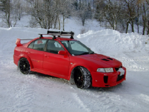
The modern tyre is a construction of three main areas. These are the bead, the sidewall and the tread. For simplicity, only radial construction road tyres will be covered here. The bead is a reinforced hoop which forms the sealing interaction with the wheel rim. The sidewall is the section of the tyre that links the bead and the tread. This varies in depth and stiffness and is generally tuned to offer specific handling characteristics on sports cars. The sidewall will flex in three main ways. The weight of the vehicle will cause it to bulge outwards locally below the wheel rim forming a flat region of tread known as the ‘contact patch’. It will also flex torsionally as the wheel is steered and laterally as the contact patch moves laterally during cornering.
The torsional flex of the sidewall will always lag behind the wheel steering movement. Shallower, stiffer sidewalls tend to flex less than deeper, softer sidewalls and generate a steering response far more quickly. The tread is attached to the carcass linking the sidewalls. It consists of a different rubber to the sidewalls, is tuned to the required grip characteristics of the tyre and will have a tread pattern consisting of blocks. There are many different styles of tread pattern, some are more continuous than a classic ‘block’ layout but all are designed to provide areas where rubber is in contact with the road and areas for surface water to be displaced to during wet conditions.
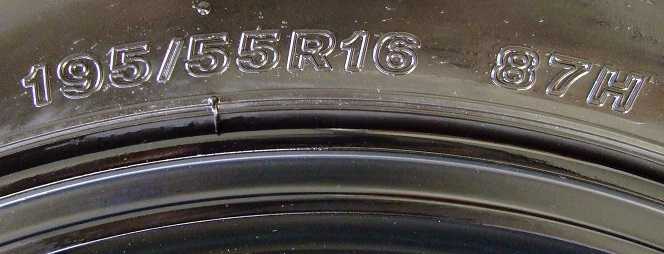
There are several markings on the sidewall of the tyre. Typical markings, using a Mini Cooper as an example, include ‘195/55R16 87H’ as well as various production codes, direction indicators and a date stamp. In the case of this tyre, ‘195’ refers to the width of the tread in mm, ’55’ refers to the sidewall section height (a percentage of the tread width and also known as the aspect ratio), the ‘R’ refers to ‘Radial’ construction and the ’16’ is the diameter of the wheel in inches. This refers to the bead seating diameter as opposed to the maximum diameter of the visible portion of the rim. The ’87H’ refers to the vertical load rating and speed rating. In this case, ’87’ refers to 545kg max vertical load and ‘H’ refers to 130mph maximum speed.
Grip
The word grip is used extensively, perhaps even excessively. Most drivers have some concept of what it refers to but very few understand how a tyre uses grip or how it is varied. Grip can be considered as the ability of a tyre to produce a force on a vehicle as a result of its interaction with the ground. Tyres generate grip through two mechanisms – mechanical and chemical. For the moment, only the total of these two mechanisms will be discussed. In conjunction with discussing the ‘contact patch’ of a tyre, a useful simplified tool to start to explain grip is a ‘grip circle’ (or friction circle). Simplified, the circle itself represents the ‘limit of adhesion’ and is a boundary that could be considered the maximum use of the available grip. To reach this boundary is to ‘saturate’ the tyre.
The diagram below shows a tyre in several conditions. The red dot represents a demand for grip. A tyre can be used exclusively for acceleration or braking or cornering. Tyres can, perhaps obviously, also be used for cornering in conjunction with either acceleration or braking. The circle is useful to illustrate that to achieve a maximum use of any one requirement there must be no use of another requirement. To blend cornering with acceleration or braking will result in a compromise and therefore less of each can be supported. It is worth noting that acceleration/braking will always trump cornering if the engine and/or brakes are powerful enough to saturate a tyre whilst cornering.
If a tyre is pushed to the limit of adhesion, some or all of the tread in the contact patch will no longer be able to grip the road surface and will start to slide. The squeal often associated with a tyre starting to slide is a high frequency sound created by high frequency oscillation of the tread releasing its grip of the road.
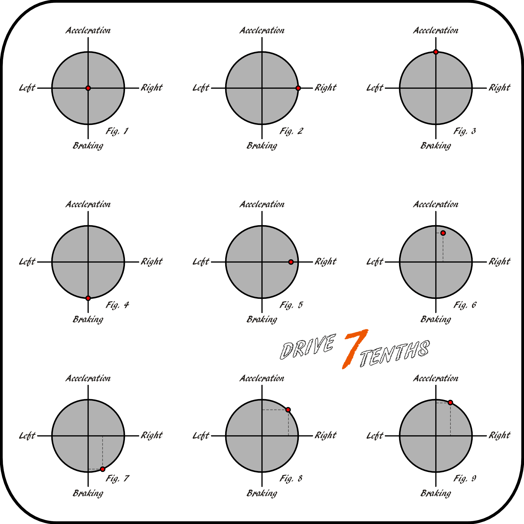
Fig. 1 shows a tyre with no grip used. Figs. 2-4 show limit cornering, limit acceleration and limit braking. This is the point at which the vehicle will start to skid in cornering, exhibit wheelspin or suffer from a locked wheel under braking respectively. Fig. 5 shows cornering below the limit of grip. Fig. 6 shows strong acceleration with some cornering but below the limit of grip. Figs. 7,8 and 9 show limit conditions but with varied blends of demand. Predominantly braking with some cornering, equal acceleration/cornering and predominantly acceleration with some cornering, respectively.
Factors affecting grip include the ‘coefficient of friction’ between tyre and road surface, the compound of the tyre, the temperature of the rubber in the contact patch, the vertical angle of the tyre to the road, tyre width, tyre pressure and aerodynamic loading to name a few. Generally, high friction surfaces, soft tyres at higher, but not excessive, temperatures vertical to the road surface with high aerodynamic downforce loading all lead to high grip situations.
Manipulating and Variation in Grip
Having introduced the contact patch and grip circles, how to manipulate or vary grip can be discussed. Firstly, the diameter of the grip circle is dictated by the vertical load that tyre is supporting. To increase the weight of a vehicle would increase the grip potential of all four tyres. (It would also require more grip to travel around the same corner at the same speed as with a lower weight.) This would be illustrated by their grip circles having a larger diameter. If inducing weight transfer, through dynamic loading of the vehicle whilst being driven, the diameters of the four friction circles representing the grip of the four tyres will vary.
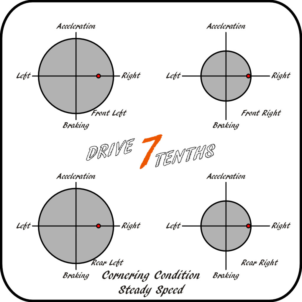
Braking, for example, will normally induce forward ‘pitch’ and weight transfer. During braking, the front tyres will support a greater proportion of the vehicle weight and the rear tyres will support a smaller proportion. As may be expected, the grip circles of the front tyres will therefore be of a larger diameter and those of the rear tyres will be smaller. The diagrams below show the four grip circles for the four tyres of a vehicle. To keep things simple the static weight distribution is assumed even across all four tyres and the tyres are considered equal.
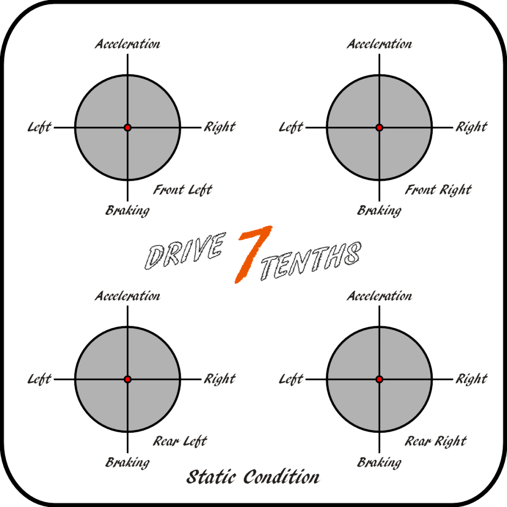
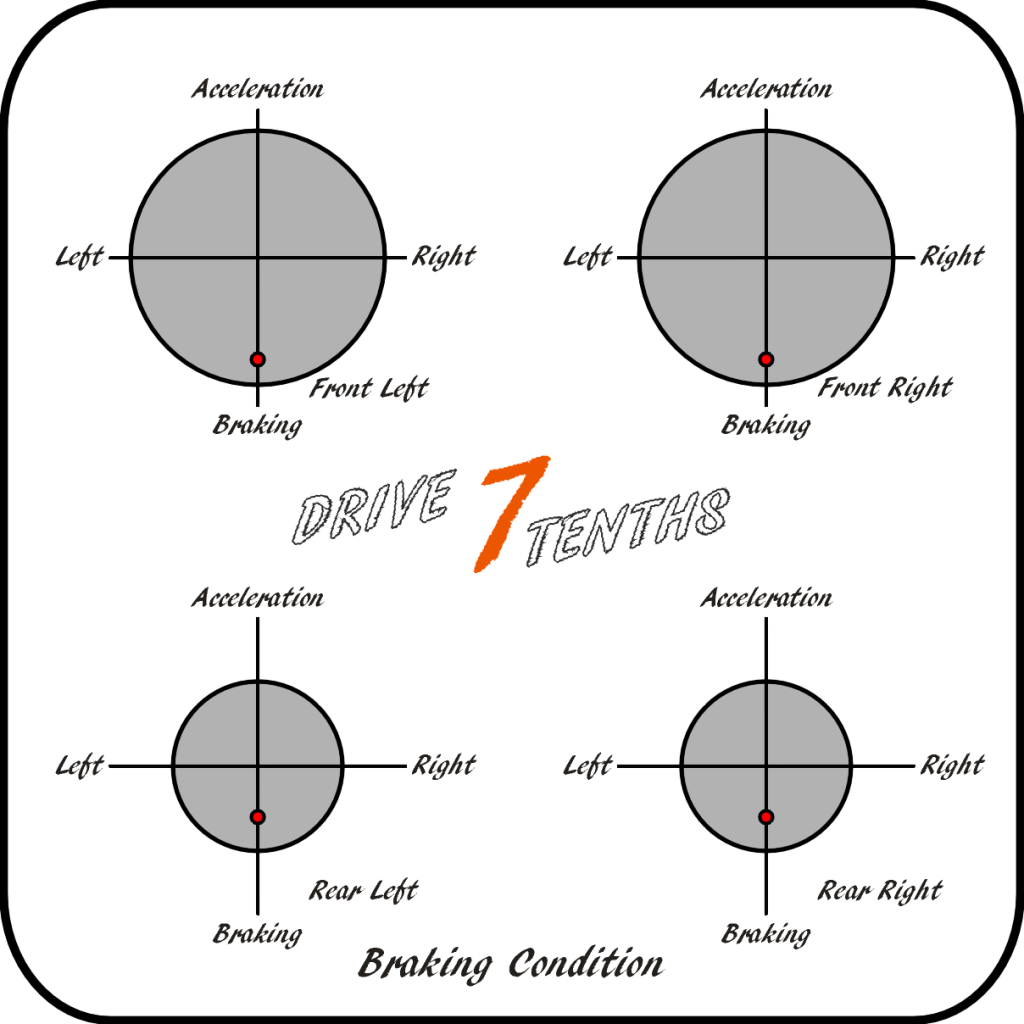
For the static condition the car is not moving and assumed on flat ground. Therefore there is no use of the tyre grip. In a simplified state, a car travelling at steady speed in a straight line on flat ground would also look like this in terms of grip usage. The braking condition shows increased front grip circle diameter and reduced rear grip circle diameter. Note the unequal positions of the red dot. (Front brakes are larger than rear brakes to account for weight transfer during braking and a similar margin of excess grip is shown for both in this diagram.)
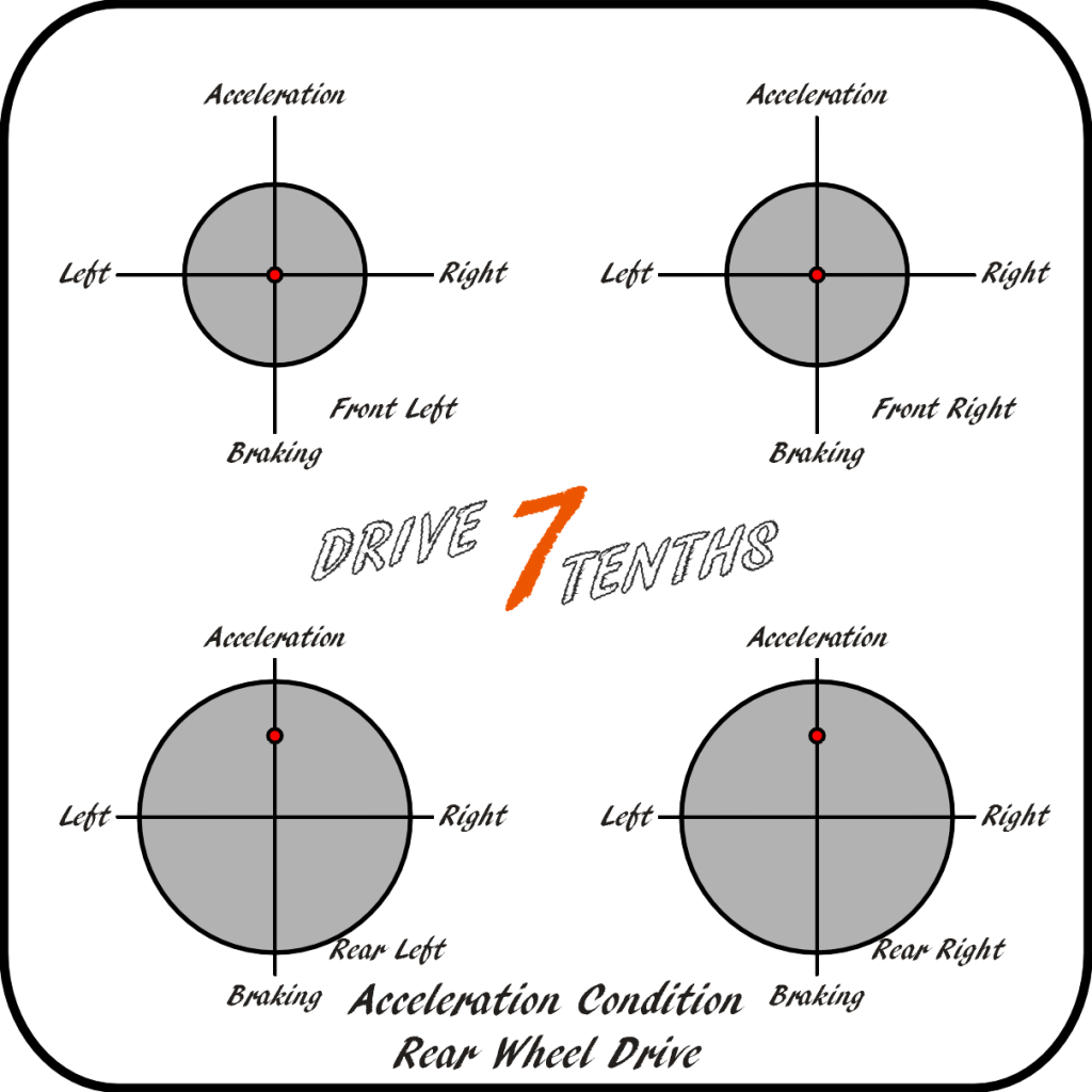
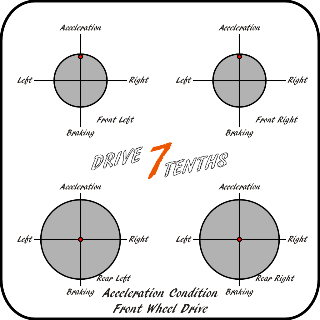
Acceleration is shown below for both rear wheel drive and front wheel drive cars. The weight transfer and change in grip circle diameter looks the same (assuming the same static weight distribution and acceleration rate etc.) but note the red dot positions are different for the driven axle. It becomes easy to see why powerful front wheel drive vehicles are often more traction limited than similar rear wheel drive equivalents. The front wheel drive vehicle requires more front grip with increasing acceleration but in fact loses this due to weight transfer. The rear wheel drive vehicle increases the rear grip potential with increasing acceleration.
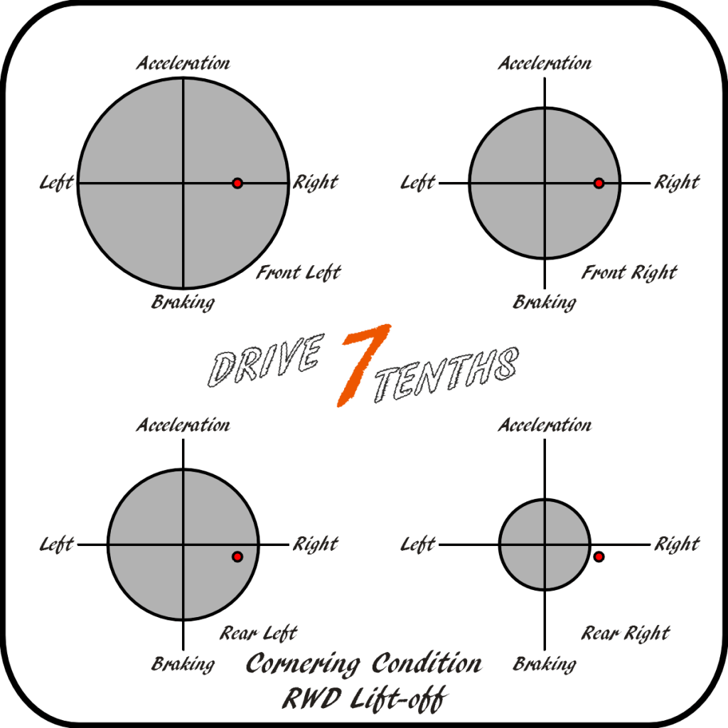
Cornering at steady speed in a right turn shows lateral weight transfer only (and grip circle diameter change). Suspension geometry effects are ignored for simplicity. Taking the same cornering state for a rear wheel drive car and then suddenly lifting-off the throttle pedal arrives at the final condition. The lateral weight transfer is unchanged but there is now forward weight transfer due to the sudden deceleration. Note the rear wheels now have some braking effect (engine braking) and the rear right tyre can no longer support the required demand. This tyre has exceeded its limit of adhesion and the car will start to spin.
As may now be apparent, the extent to which a vehicle is cornering, braking or accelerating (or a blend of these) will affect the instantaneous total grip available at any one tyre’s contact patch due to weight transfer. The driver can use this manipulation to their advantage upon understanding how a change will affect the vehicle.
Naturally, there are further levels of complexity than those covered so far. The main conclusion to draw from this section is that weight transfer affects grip circle diameter (total available grip) at any one tyre and that blending cornering with either braking or acceleration affects how grip is ‘spent’.
Slip Angles and Sideforce
The term ‘slip angle’ is less commonly used than ‘grip’ and tends to be discussed solely by engineers and racers. The first thing to consider is the direction a tyre is pointing (and rotating in). A tyre that is rolling in the direction of travel cannot generate a cornering force. It can only develop forces for acceleration or braking.
In order to generate a cornering force, a ‘sideforce’, the tyre must be turned relative to the direction of travel. Essentially, it must slip. The tyre’s slip angle refers to the angle between the direction a tyre is rotating in and the direction of travel of the vehicle. As rubber on the tread is rotated around towards the contact patch it is free and generating no load. As a section of rubber (perhaps imagine an individual tread block) moves into, and becomes, the contact patch it will now start to fight against the ground that is moving at an angle to the original direction.
Perhaps unsurprisingly, this angle is again the slip angle. Since rubber is a flexible material, the portion moving now rearwards from the front of the contact patch will flex to the side. Each individual section of rubber will flex further and further to the side as it moves towards the rear of the contact patch. Below the ‘limit of adhesion’ the rubber will spring back to the unloaded position as soon as it exits the contact patch. This flexing of the rubber generates a reactive force – a ‘sideforce’.
It is beyond the scope of this section but increased slip angle will generate increased drag on the vehicle as well as increased sideforce. This can be illustrated by holding a steady throttle position to maintain a constant speed on a flat section of tarmac in a straight line and then gradually steering to one side in an ever decreasing radius. With the throttle constant the engine power output is constant, but as the slip angle is increased with more steering wheel rotation, the car will slow down due to the extra drag.
Tyre Wear
Heavy tyre wear for any given compound is a result of two main influences – the distance the rubber is slid against a surface and the temperature. To keep things simple only a road tyre will be discussed. Since below the ‘limit of adhesion’ the tread of a tyre and its tread blocks are rolling around with the wheel, through the contact patch (with or without some flex/deformation) and round again on a continuous cycle, there is no sliding of the rubber against the road surface. The wear will be related to how hard the tyre is being worked. Once a tyre is loaded to the point that it starts to slide in cornering or is suitably bunched in acceleration or braking it will wear at an accelerated rate.
The video below is a brilliant illustration of the tread bunching and then releasing under acceleration. It is the other way that a sidewall may flex that was not mentioned in the ‘Construction, Sizing and Ratings’ section.
Using Tyres for Cornering
To keep this section relating to tyres and not covering the whole of vehicle dynamics, two key areas are going to be covered. Firstly, the concept of centripetal force, and secondly, how tyres develop this for a car travelling around a corner.
The simplest way to illustrate centripetal force is either to discuss satellites orbiting The Earth or swinging a conker on a string. Quickly considering Newton’s laws of motion we can appreciate that the moving satellite requires a force towards the centre of its orbit (centre of The Earth) to prevent it shooting off into space in a straight line. In this case it is a gravitational force. In the case of the conker, the faster it is swung the more tension (force) builds up in the string. If not holding it very tightly, at some point the string will slip through the fingers and the conker will fly off in a straight line! In this case, the tension in the string is the force required to keep the conker travelling a constant radius.
Centrifugal force is often talked about as the force aiming to throw an object outwards. In fact it is centripetal force that is required to make an object travel around a curved path. Without this, it will travel in a straight line at whatever speed it was travelling at before the force was removed. Therefore the word centrifugal will not be used again.
What may be becoming obvious is that a car’s tyres develop centripetal force towards the centre of a given radius or corner. In fact, in very simple terms (ignoring wheelbase and steering geometry) it is the total of the ‘sideforce’ produced by all four tyres. However it may not be clear why it is all four tyres and not just the front tyres that generate this sideforce.
Initially the car is travelling in a straight line. Turning the steering wheel to introduce a slip angle at the front tyres will generate a sideforce. Acting about the ‘centre of mass’ of the car (for simplicity, assume this is midway between the front and rear axle centrelines) this force will cause the body of the car to rotate and ‘turn-in’. As soon as this starts to happen, the rear wheels are changing their direction to the original direction of travel and therefore are receiving an induced slip angle. So as the car turns, this rear wheel slip angle increases and generates its own sideforce.
Comparing the total sideforce of each axle about the centreline to a see-saw with a person sitting at each end it becomes simpler. Initially we had force only at one axle (a person on one end of the see-saw). Then the rear axle started to generate force (the other person begins to lower their weight progressively onto their end of the see-saw). Once both forces about the centre of mass/rotation are equal, we have a state of equilibrium (balance). The see-saw is now level with two people of equal weight at the same height. The car has no rotation about its centre of mass but has sideforce at all four tyres generating centripetal acceleration towards the centre of the corner and therefore can drive around the bend.